


FTTX service Project construction analysis
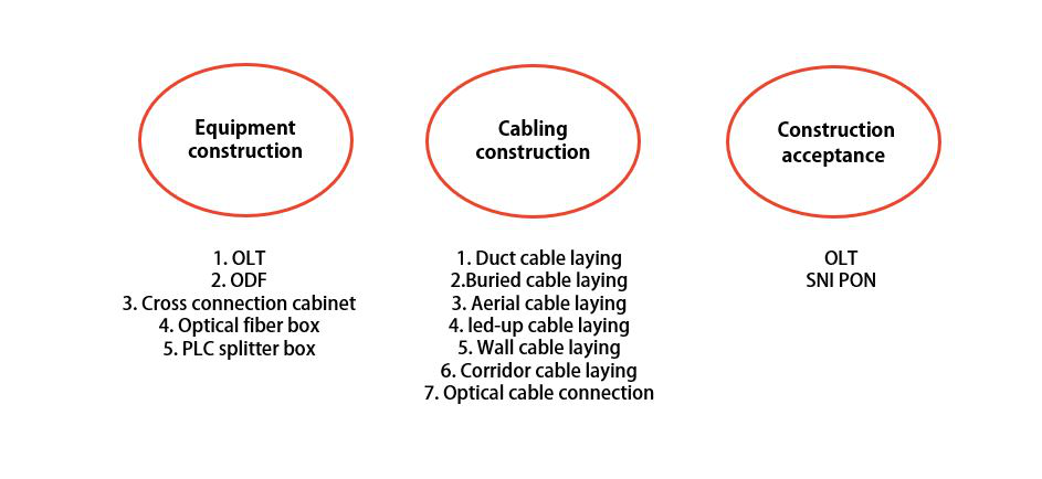
Equipment construction:
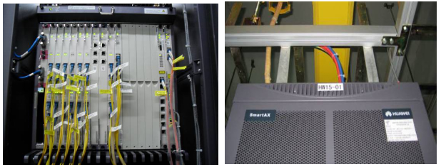
1>OLT construction
The position and direction of the rack installation should meet the design requirements.
The rack installation should be firm, installation clearance should not be greater than 3mm, and the vertical deviation should not be greater than 1‰ of the rack height.
The rack should be reinforced with expansion bolts to the ground.
The rack installation must be seismically reinforced if location in seismic intensity above 7 degree.
The mounting of the sub-rack shall comply with the design regulations.
Sub-rack and rack reinforcement should meet equipment assembly requirements.
The sub-rack installation should be firm and neatly arranged. With good plug-in contact.
Wall-mounted equipment should be installed firmly, horizontally and vertically, the height of the bottom from the ground should meet the design requirements.
The rack identification should meet the requirements which with label uniform and clear.
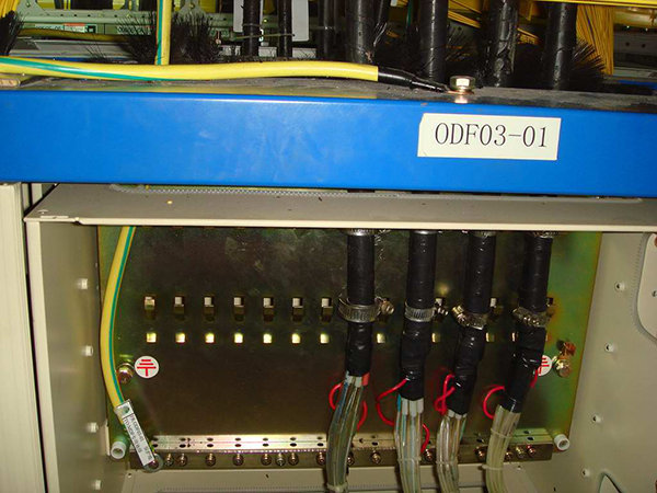
2>ODF construction
The installation of the ODF rack:
1 The installation position and direction should meet the design requirements.
2 The vertical deviation of the installation should be no more than 1‰ of the rack frame.
3 The adjacent racks should be close together with clearance less than 3mm;
The laying of the optic cable:
1 The model of the fiber optic cable should meet the design requirements with remaining length not exceed 1m.
2 The layout should be neat and tidy.
3 The static radius of curvature should be no less than 30mm.
The lightning protection grounding:
1 ODF rack enclosure equipment protection ground using multi-strand copper wire 16mm2 or more;
2 ODF grounding must be separated from the grounding in the equipment room, then connected to the general earthing bar.
3>Cross connection cabinet construction:
The foundation of the cross-connection cabinet should be compacted, and the cement plastering surface should be smooth without damage or cracking. The vertical deviation of the cabinet after installation should less than 3mm, the outer edge of the basement 150mm larger in width and length as well as height of the basement should be 300mm from the ground.
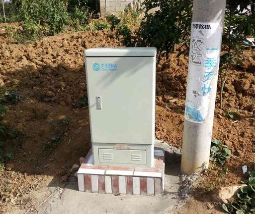
The grounding installed according to the design. خ¦60*1700cm galvanized steel pipes used for grounding welded into the ground with 40أ—4 flat steel. After cable is laid, the grounding must be reliable firm.
4>Optical fiber box construction
Optical fiber box construction need ensure if the box stable, any enough connection areas in the box to meet the storage and distribution during the connection. Different types of cables should have relatively independent inlet/outlet holes. The capacity should meet the requirements of full configuration. The cable should be sealed with fireproof mud.
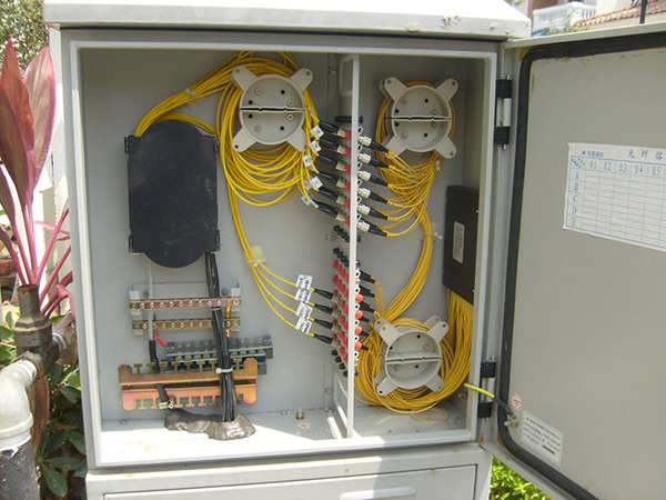
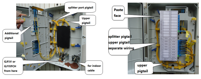
5>PLC splitter box:
1. Indoors installation, the fiber cable could be entering from the top, with additional 3-5 meters above the box, then set in protection tube after fixing.
2. Outdoors installation, the fiber cable must enter from the bottom, with additional cable 3-5 meters. After fixing then install the protection tube.
Cabling construction:
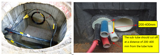
1>Duct cable laying
Duct cable laying should meet the following requirements.
1. For different pipes with a hole diameter of 90 mm or more, three or more sub-pipes shall be laid at one time between the holes according to the design regulations.
2. When cable through different pipes, the inner diameter of the pipe should be not less than 1.5 times than the outer diameter of the cable.
3, Artificial laying of optical cable should not exceed 1000m. The optical cable laying in one direction generally does not exceed 2000m.
4. The cable after laying should be straight, no twist, no obvious scratches or damage.
5. The bending of the cable outlet hole within 150mm shall be prohibited.
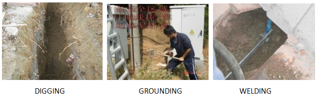
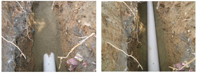
2>Buried cable laying
Buried optical cable should meet the following requirements:
1. The radius of curvature of the direct buried cable should be greater than 20 times than the outer diameter of the cable.
2. The optical cable can be laid together with other optical cables. It must not overlap or cross. The parallel clearance between cables should be ≥100mm.
3. In slopes area which greater than 20آ° and lengths greater than 30 m, should use “Sâ€-shaped laying. When laying on long slopes with slopes greater than 30آ°, special structural cables (generally steel wire armored cables) should be used.
4. The protection pipe after buried optical cable passing through should be tightly sealed.
5. All various signs of the direct buried optical cable shall be in marked according to the design requirements.
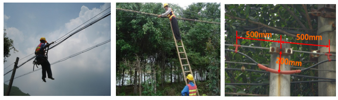
3>Aerial cable laying:
First of all, ready for safety protection before aerial work.
It should be naturally straight and kept away from tension, stress, twist, and mechanical damage after the aerial cable laid.
The distance between the cable hooks should be 500mm with tolerance آ±30mm.
4>Led-up cable laying
Check the pole and the wiring location.
Find cable protection sub-tube and steel pipe about 4 meters.
Both buried into the ground 40 to 60 cm and fixed. Pull the cable out of the pipe and fixed.
The length must be in accordance with national regulations.
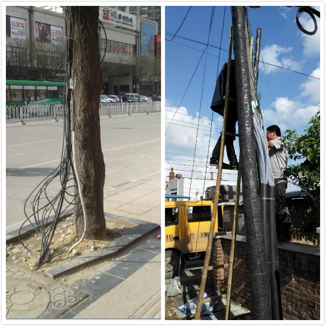
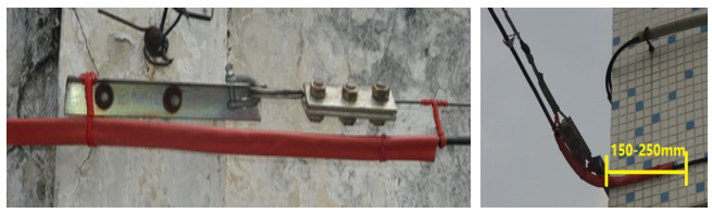
5>Wall cable laying
The laying of wall cables shall meet the following requirements:
1 It is not advisable to lay armor or oil cable on the wall.
2 The height of the wall cable should be no less than 3m from the ground. The crossing of the street and courtyard should be carried out by steel strands. The lowest point of the cable should meet the design requirements.
3 The horizontally laid suspension wire shall be fixed at the terminal on the wall and the intermediate support shall meet the requirements.
4 The distance between the wall supports should be 8~10m, and the distance between the terminal fixture and the intermediate support should be ≤5m.
5 The distance between the hooks on both sides of the wall aerial cable shall be 150-250mm, and the distance between the two sides shall be equal.
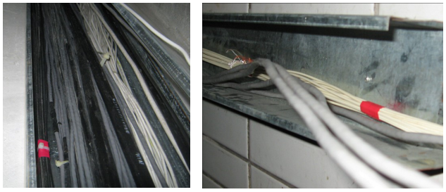
6>Corridor cable laying
Cables laid in the corridors usually with 2 types, duct channel and concealed pipes.
1 Both should meet the requirements of the design documents.
2 It is advisable to use the mark on both ends.
3 The pre-embedded channel should be steel material, with cross-section utilization 30% to 50%.
4 When laying more than 4 cores cables, the diameter cross-section of the straight pipe utilization should be 50% to 60%, curved pipe 40% to 50%. When laying 4 cores or below, the cross-section utilization ratio of the pipe should be 25% to 30%.
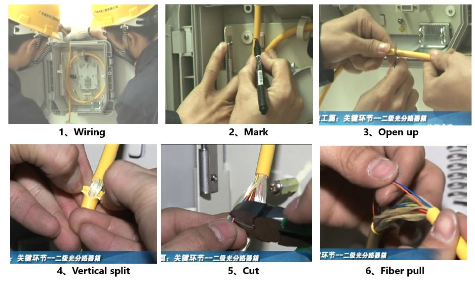
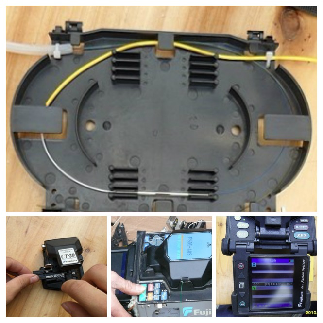
7>Optical cable connection
1. Preparation: Should be dustproof, waterproof and shockproof
2. Ready to work
3. The cable connector fix and ensure the cable will not loose.
4. Cable pulling off preparation
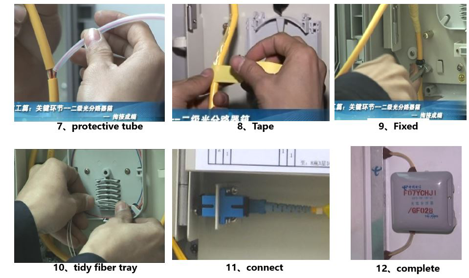
5. Fiber cable core fusion: Keep the table and fusion machine clean and connection in order.
6. Fiber protection tube heating.
7. Fiber splicing.
8. Fiber splice box packaging.
Construction acceptance:
OLT device SNI port optical interface average transmission optical power
Expected results: luminous power -11.5 to +3dBm
OLT device SNI port optical interface receiving sensitivity
Expected result: Receive sensitivity ≤ -19dBm
OLT device PON port downlink average transmission optical power
expected outcome:
When the OLT optical module is 1000BASE-PX10: -3 to +2dBm.
When the OLT optical module is 1000BASE-PX20: +2 to +7dBm
OLT device PON port receiving sensitivity
expected outcome:
When the OLT optical module is 1000BASE-PX10, the maximum is -24dBm.
When the OLT optical module is 1000BASE-PX20, the maximum is -27dBm.
ONU device PON port uplink average transmission optical power
Expected results: -1.0 to 4.0dBm
ONU device PON port receiving sensitivity
Expected result: sensitivity ≤-24dBm